
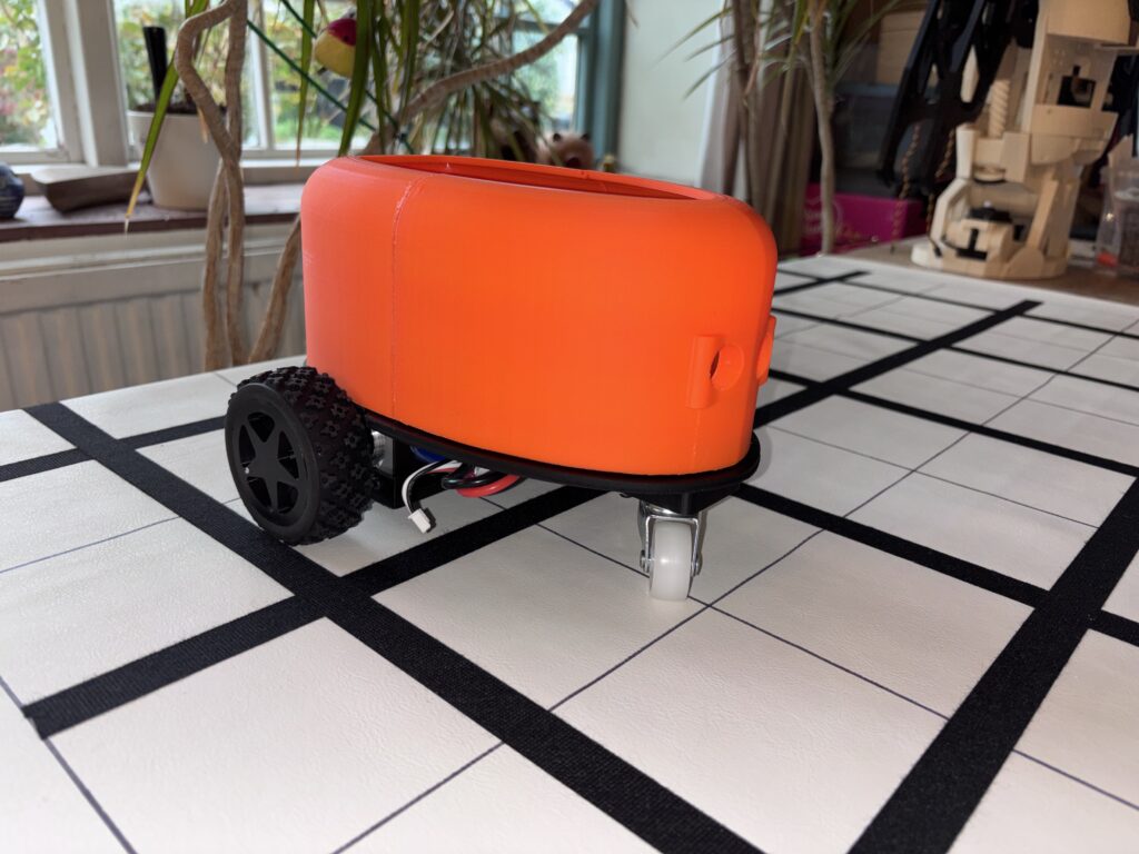
The RixBot has had an update, both in terms of hardware (improved circuit board), software (much improved code) and some slight modifications to the body. The new version has an orange body, but is essentially the same otherwise. The image below shows the robot buggy on the grid system (see below) it uses to move around on. The wheels are slightly larger than the original:
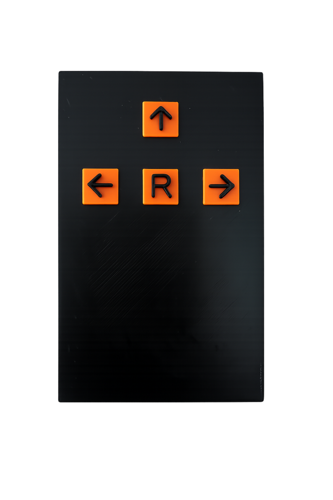
The original controller for the RixBot is a simple four button handheld unit, which has buttons for Forward, Left, Right and Run. The idea is to program the buggy using the three directional buttons, then press the run button (marked ‘R’) to execute the sequence of instructions.
Voice Controller
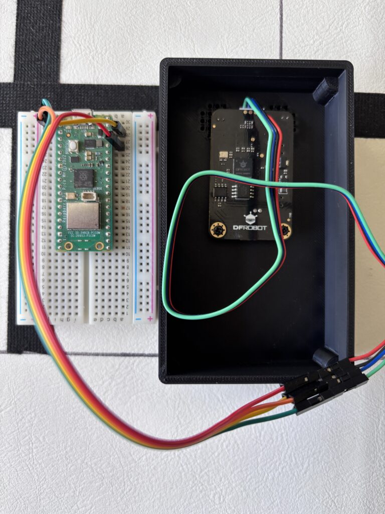
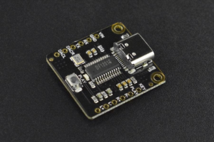
With the new buggy there is a new controller which uses voice commands. It is the same size as the original hand controller, but has no buttons. Instead, it has two microphones internally which pick up voice commands. At present , it uses an off-the-shelf DFRobot Gravity ‘Offline Voice Recognition Sensor’ connected to a Raspberry Pi Pico, which send the commands via Bluetooth to the buggy. The voice recognition unit does work, but only under the right conditions – if there is a lot of background noise, then it does not seem to pick up the commands. The image below shows the very simple internals of the voice recognition box (minus the battery, switch and charger) when it was being tested out with the Pico.
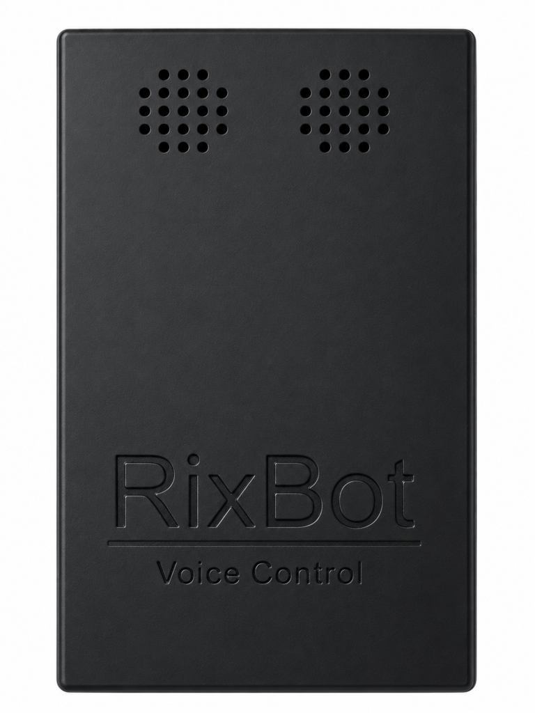
The front of the box (below) just has some holes where the two microphones are located inside (attached to the Gravity voice recognition unit).
The idea behind the voice control box is to provide an alternative to the handheld unit in cases where the user might not have the manual dexterity necessary to press the buttons on the other handheld unit. It works in the same way – you speak out loud the sequence of commands, such as, for example:
Forward, Left, Forward, Right, Forward, Forward
It has only been bench tested so far and still needs to be taken out to the Rix Office to try out with a group of participants, which will hopefully be soon.
Line Following Grid
Originally, we wanted the buggy to move around independently within a 5 x 5 grid, the idea being that you can program the buggy to move from a designated start square to a destination square by sending commands to the buggy with the handheld controller. For instance, suppose that you would like the buggy to move from the bottom left square to the top right square:
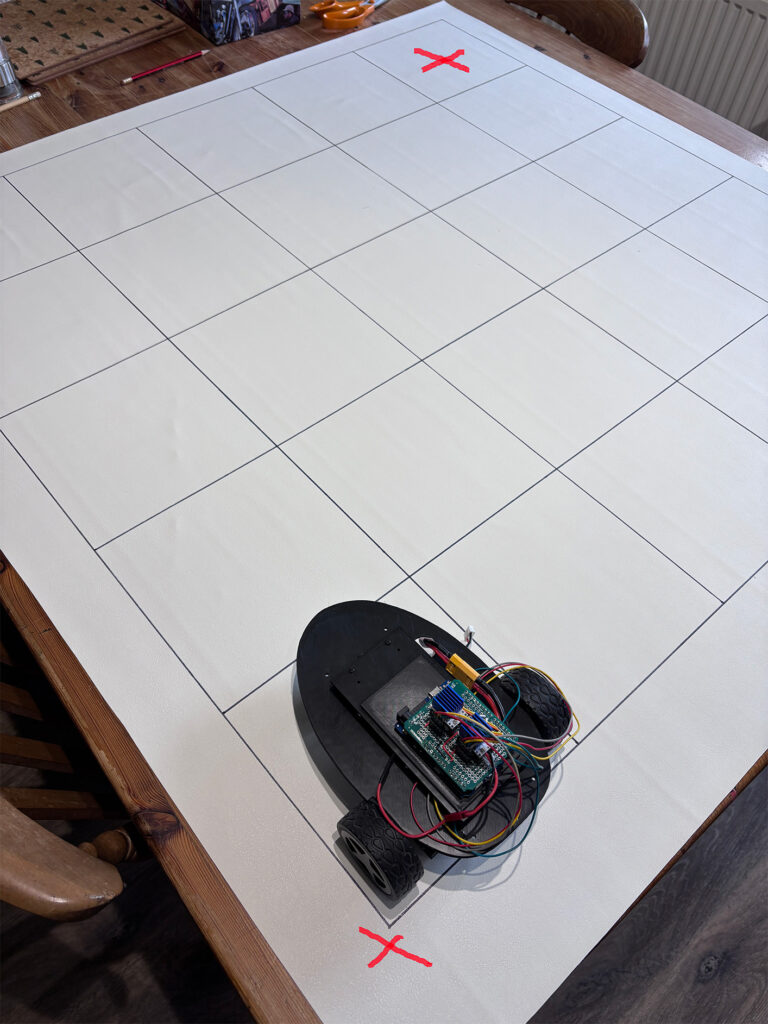
As an example, for a completely blank grid a sequence of instructions to move from bottom left to top right could be (Forward: F, Right: R):
F, F, F, F, R, F, F, F, F
Whilst this did work to a limited extent, the buggy tended to drift and did not stay on a straight line. Even if the buggy was a few degrees out from pointing directly forwards, by the time it reached the last square of the grid it could end up being up to 20mm to one side or another. These errors then accumulated, and the buggy could end up between grid squares instead of inside. Hence we looked for a more robust system to keep the buggy on track and within the grid squares.
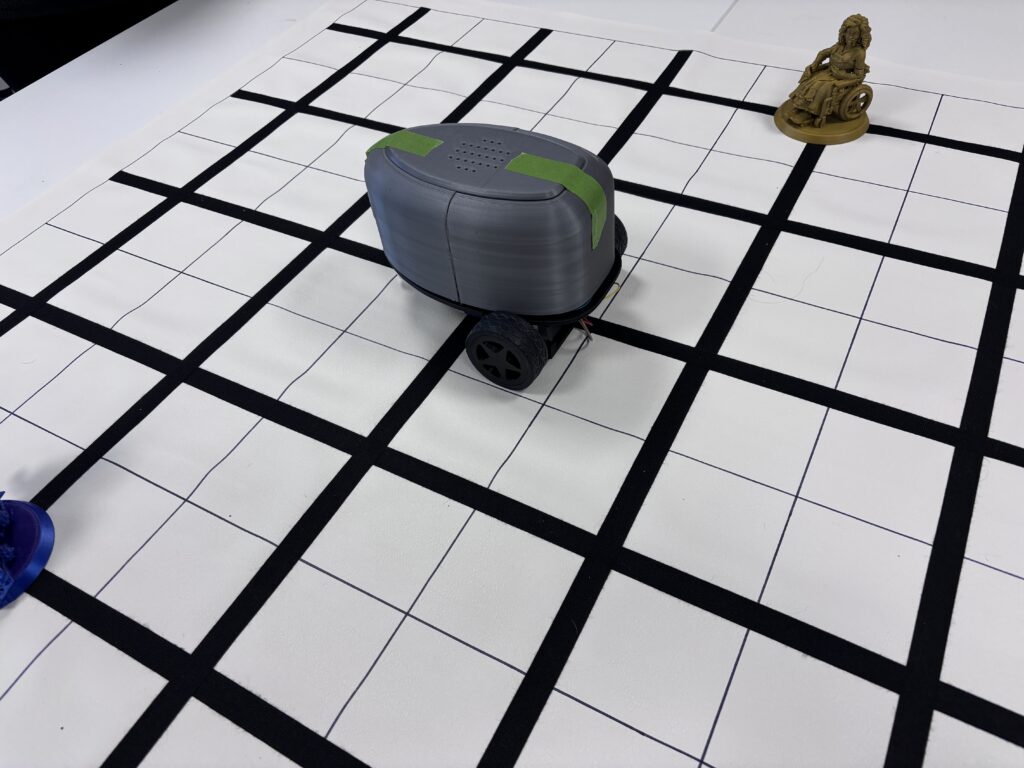
The solution was to add lines to the grid which the buggy could follow using a QTR reflectance sensor – a line following sensor. This is shown below, with the original buggy being tested for tracking. We added a few obstacles to make programming a little more interesting.
How does Line Following Work?
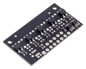
Beneath each of the buggies there is a QTR-MD-05A reflectance sensor which is mounted so that the sensors point downwards towards the grid. This little module essentially consists of five IR LED/phototransistor pairs. The QTR-MD-05A reflectance sensor (see below) helps the buggy to ‘see’ a black line on the grid surface by shining infrared light downward and measuring how much light bounces back.
Here’s the simple version of how it works:
- Light surfaces (the white background) reflect a lot of infrared light.
- Dark surfaces (the black tape) absorb more light and reflect less.
The sensor constantly checks this difference and sends readings to the Arduino microcontroller, which will then correct the direction of the buggy if it moves too far either side of the line it is following. Essentially, if the sensor sees the black line, it gets a ‘dark’ reading; if it moves off the line onto the lighter floor, it gets a ‘light’ reading. The code compares the sensor readings and adjusts the motors:
- Drift left → steer right
- Drift right → steer left
- Centered on the line → drive straight
Audio Output
The buggy is designed to be as inclusive as possible, using multiple modalities for both input to the buggy and user feedback from the buggy. Currently, these are being explored at Rix Inclusive Research, where we are looking at the different possibilities for interacting with robots, how to communicate our intentions and what robots can be used for to improve our lives – see the article Inclusive Robotics Workshop.
The buggy currently uses audio output to acknowledge and respond to what it is currently doing. This is very helpful for blind users controlling the RixBot, so that it is clear what step of the sequence of instructions is being carried out, and which direction it is pointing in.
Audio output is provided by a DFRobot Fermion MP3 player, attached to the Arduino.
Responses were generated using an AI speech generator and uses a British female voice. When the buggy begins to move, it will play an audio clip that states the command currently being executed, such as ‘Moving forward’ or ‘Turning left’. When the command has been executed, it is followed by an audio clip that states its current direction. This is very helpful when programming the sequence of moves, since it is quite easy to lose track of which direction the buggy is currently pointing in.