One of the most enjoyable parts of robotics is discovering how much intelligence you can create using very simple hardware.
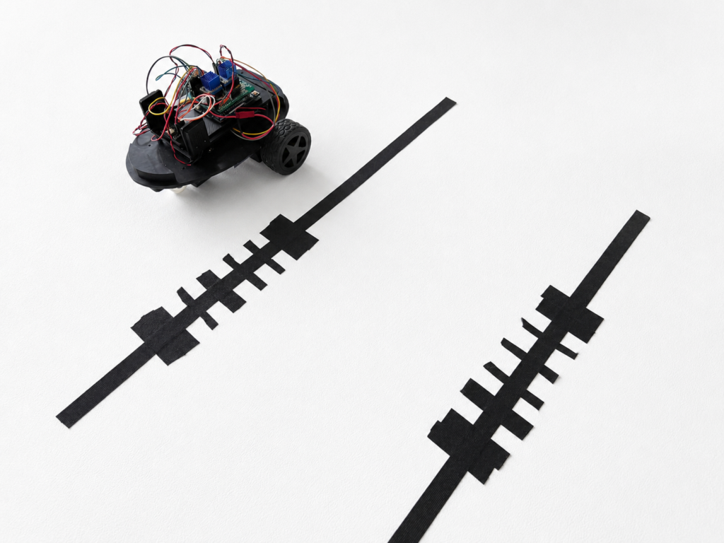
Recently, I’ve been experimenting with a small line-following robot buggy built around an Arduino-compatible controller, a QTR-5A line sensor array, and a Bluetooth hand controller. Originally, the buggy could receive movement commands such as forward and left/right turns. However, I decided to simplify the design and explore something more interesting:
Could the robot follow a line continuously and trigger actions by reading symbols placed on the track itself?
The answer turned out to be yes and surprisingly elegantly too.
Simplifying the Robot Buggy (RixBot)
The first step was to reduce the control system to just two simple Bluetooth commands:
GO – begin following the line
STOP – halt the robot
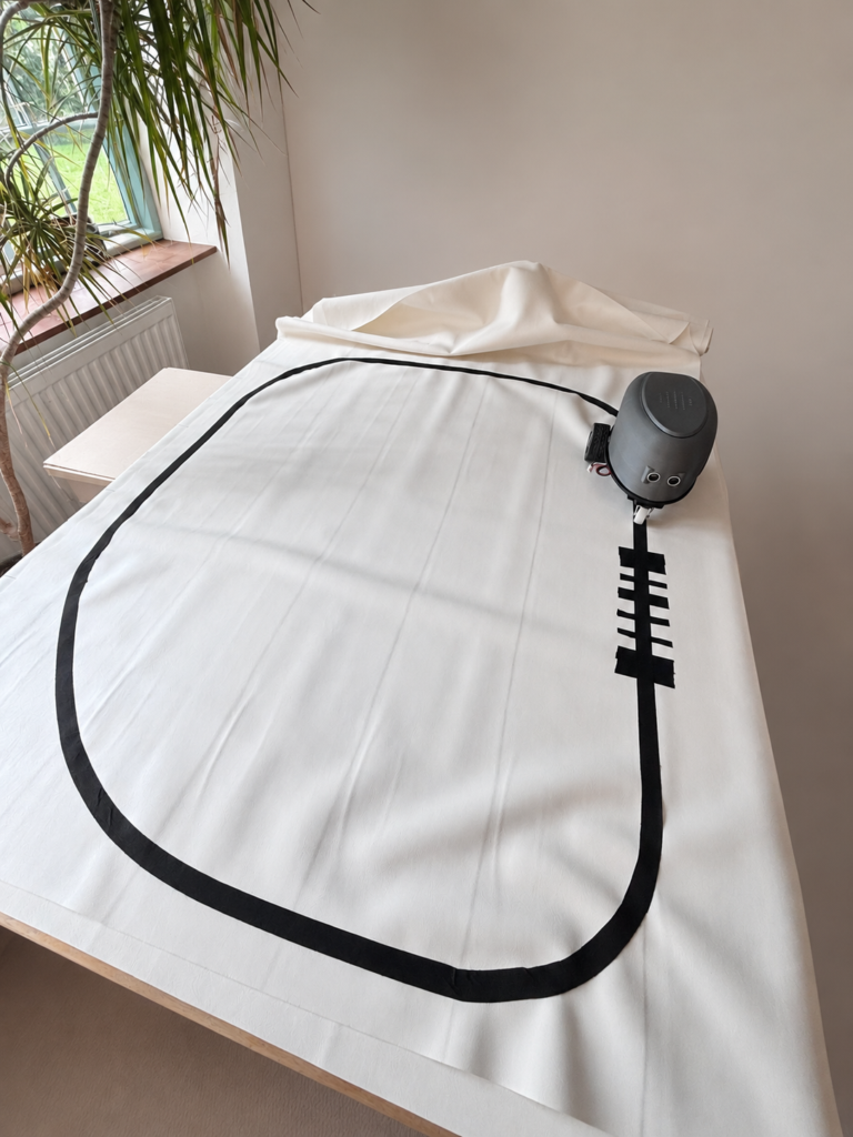
Once moving, the buggy continuously follows a black tape line on a white surface using the QTR-5A reflectance sensor array mounted underneath the body. This simplified approach made the robot much more reliable and created an excellent platform for experimentation.
From Line Following to Symbol Reading
Instead of trying to recognise complicated visual symbols such as QR codes or arrows (which need a camera), I designed a much simpler system that was inspired by supermarket barcodes.
The idea is straightforward:
- the robot follows a black line
- additional strips of black tape are placed across the line (transverse)
- the robot buggy interprets the width and order of these strips as data
The result is a kind of line-robot-readable barcode language.
How the Barcode System Works
The robot reads the barcode while driving over it. It moves along the black line, as normal, using the QTR sensor array to track the line. When it reaches a ‘barcode’ it then triggers an audio file to be played.
Each barcode consists of:
- a START marker (two thick black lines)
- four data bars (either a single line of black tape, or a half thickness of tape)
- a STOP marker (two thick black lines)
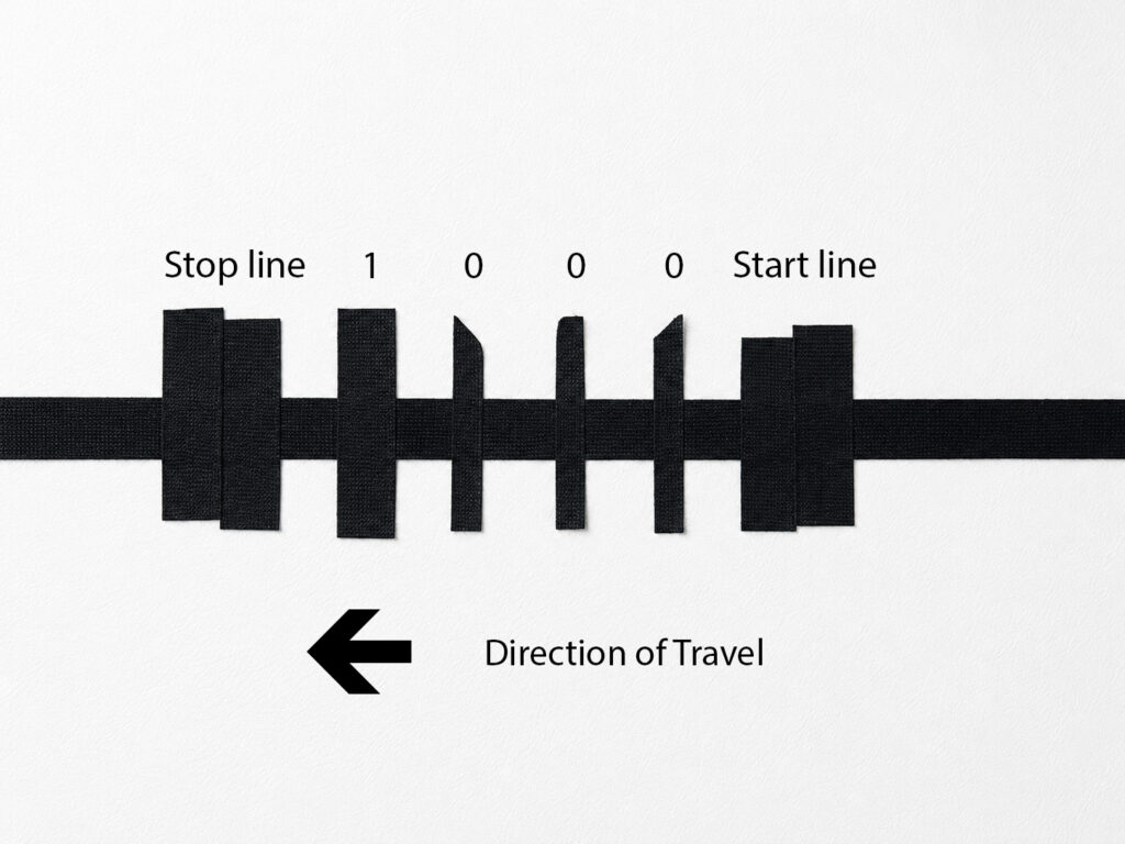
Each bar crosses the main black line at right angles. The layout looks like this:
The robot measures how long each black bar is visible underneath the sensors. The strip on the right begins with two strips of tape (the start line), three thin strips and a medium strip (the data, representing in this case the number 1 in four bit binary) and then two more strips of tape (stop line).
Bar Widths
Different tape widths represent different values:
Tape Width Meaning:
- Narrow bar is Binary 0
- Medium bar is Binary 1
- Wide bar (two strips of tape) START / STOP
Using four binary data bits allows up to 16 unique commands, which is more than enough for the current project. The image below shows one of the barcodes – in the direction of travel indicated, the buggy encounters three thin bars followed by a thicker bar. This represents the number 0001 in binary, which is equal to the number 1.
Adding Audio Playback
The exciting part comes after the barcode is read. The robot is connected to a small DFRobot Fermion MP3 playback module, which can play audio files stored in the memory chip of the player. Each barcode maps to an audio track:
| Barcode | Action |
|---|---|
| 0001 | Play audio file one.mp3 |
| 0010 | Play audio file two.mp3 |
| 0011 | Play audio file three.mp3 |
| 0100 | Play audio file four.mp3 |
When the robot detects the STOP marker, it:
- completes the barcode read
- plays the corresponding audio file
- stops moving
This effectively turns the robot into an interactive storytelling or educational platform by choosing which order to play the audio recordings. A more sophisticated version (using Raspberry PI) could allow for the recording to be made on the fly, and then choosing where to place the barcodes.
Why This Approach Works Well
One of the clever aspects of this system is that the robot does not need a camera or image recognition software. Instead, it uses simple reflectance sensors, timing measurements and a small amount of logic.
This keeps the project inexpensive, reliable, easy to understand and ideal for education. Someone with a rudimentary understanding of robotics could build this. Furthermore, it is easy to make the barcodes – just a bit of black tape and a pair of scissors.
It also demonstrates an important robotics principle sophisticated behaviour can emerge from very simple sensing systems.
Future Possibilities
Now that the basic robot barcode reader is working, there are many directions the project could take. In the first instance, the robot and barcode system will be used for a workshop at the Newham SEND Young Peoples’ Festival:

There are also other possibilities too:
- museum-style guided exhibits
- interactive floor maps
- storytelling robots
- educational games
- or robots that perform actions at specific track locations
Future versions may include:
- more complex barcode formats
- branching routes
- wireless content updates
- sound effects
- synchronised lighting
Final Thoughts
What started as a simple line-following buggy has evolved into a robot capable of reading commands directly from the environment around it. And all of it is done with:
- black tape
- a few sensors
- some carefully designed timing logic
Sometimes the most satisfying robotics projects are not the ones with the most advanced hardware, but the ones that creatively use simple tools to produce surprisingly intelligent behaviour (essentially whatever I had in my cupboard). It was fun testing the buggy on a continuous circuit. The challenge I made for myself was to send the buggy around the track and then quickly swap the bar code for a different one before it came around again. Easy with just one barcode, but gets progressively harder with two or more.