Category: Robot Programming Made Simple

  • RixBot Update

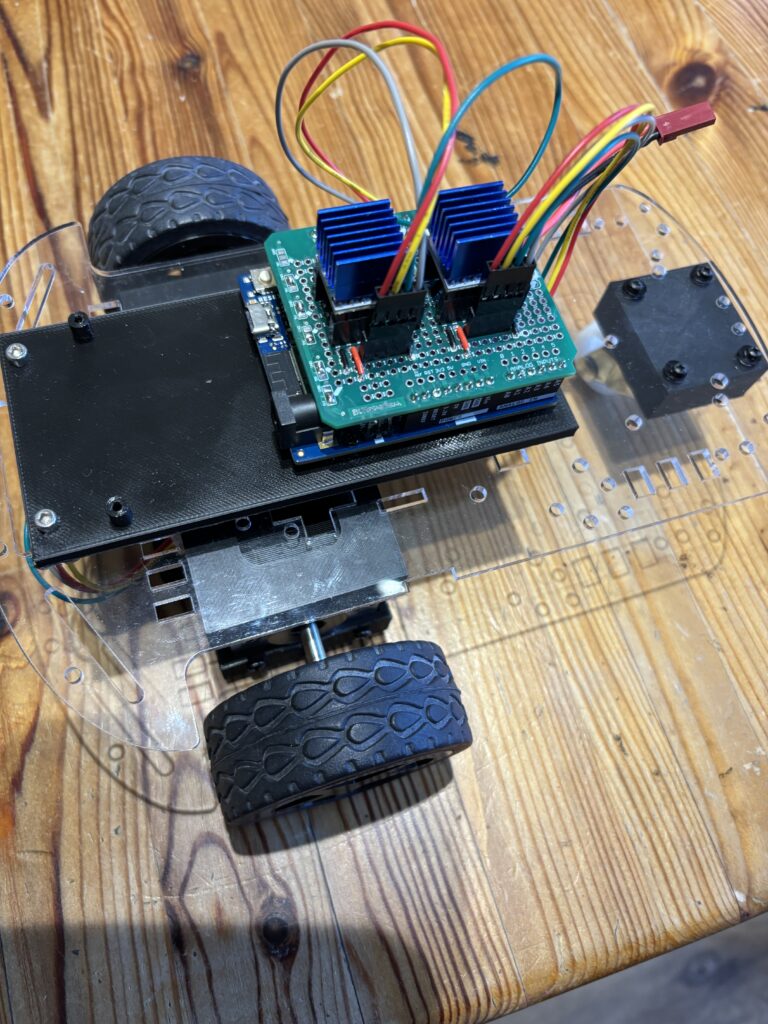
    Work has been ongoing for a new version of the RixBot throughout December, mostly looking for ways of improving the accuracy of the movement and different ways to program the robot buggy. The first update involved changing the types of motor used to drive the buggy from simple DC motors (not very accurate) to stepper motors, mainly because of the accuracy when using steppers. I already had a pair of Nema 17 stepper motors from a former project, and an old buggy chassis made from acrylic.

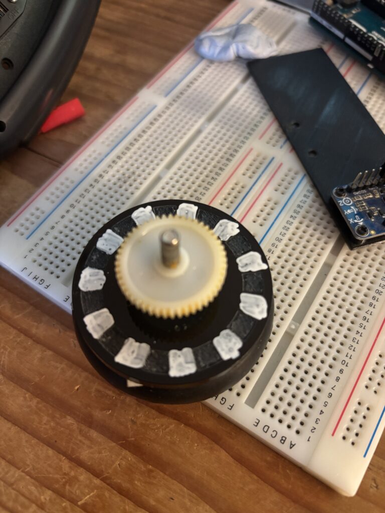
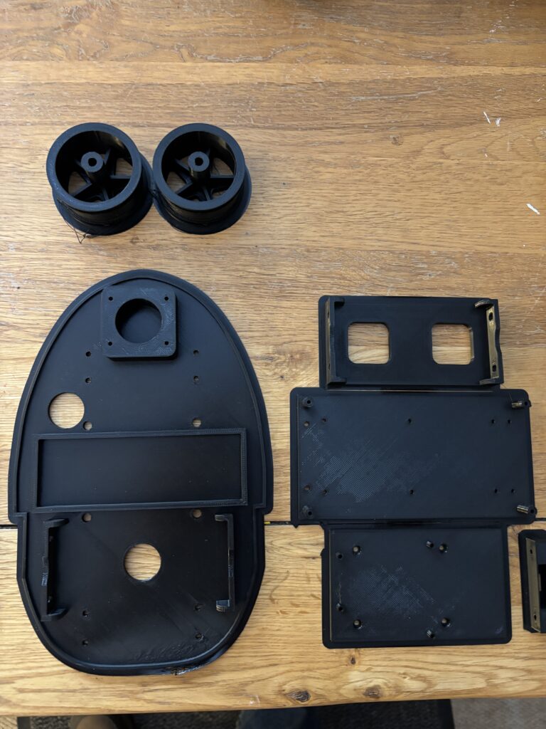
    Unfortunately, the wheels supplied with the acrylic buggy did not fit onto the stepper motors, so a new pair that would fit onto the ‘D’ shaped shafts were 3D printed:

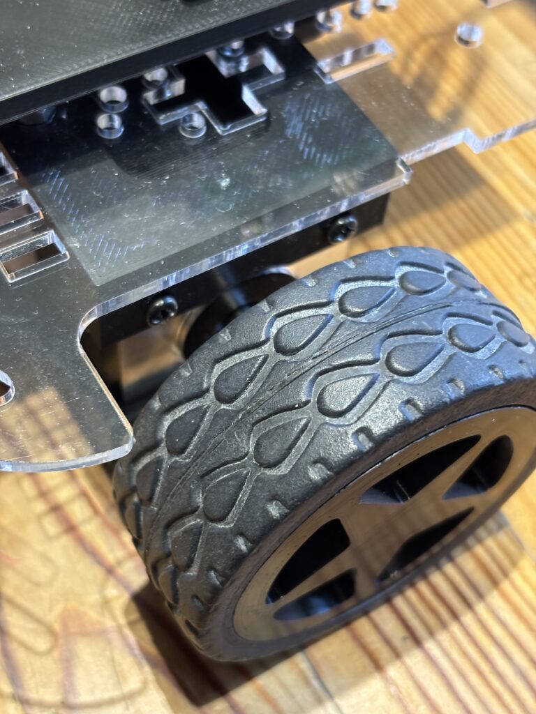
    The tyres off the old wheels were reused and placed onto the new 3D printed rims, as you can see above.

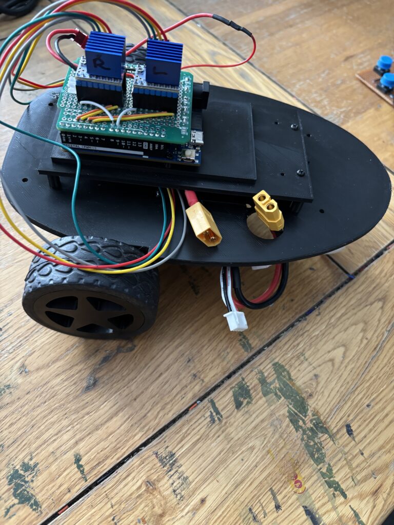
    To drive the stepper motors, a pair of TMC2208 stepper drivers were used as they are much quieter than the alternatives (such as A4988s) and work really well:

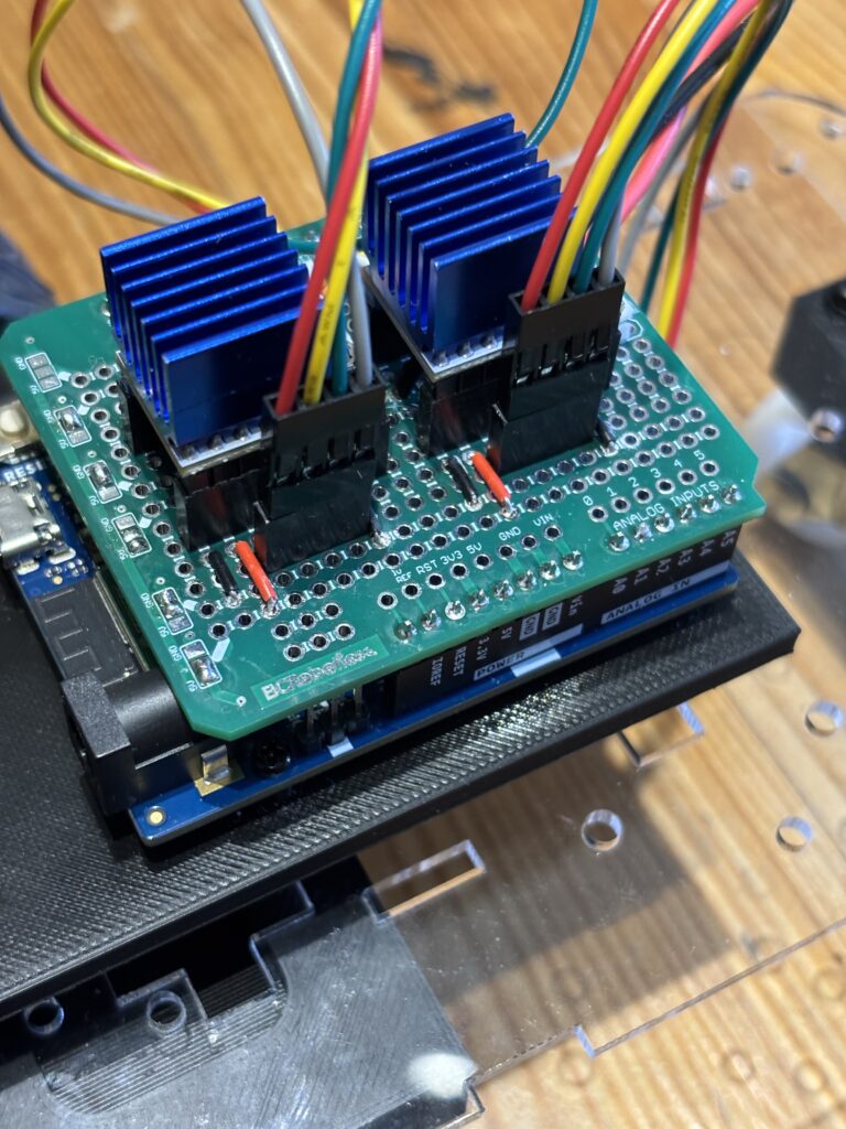
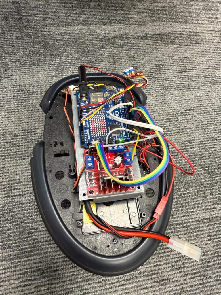
    The whole buggy is controlled through one of the new generation Arduino Uno R4 wifi microcontrollers, which has built-in bluetooth low energy. The stepper controller were mounted on a custom shield for the arduino (see above) that was constructed from a simple prototyping board. This particular board is made by BC Robotics, and an excellent prototyping shield for the uno. Unfortunately, they are a bit difficult to get hold of at the moment, so I am developing one of my own,

    To power the stepper motors, an 11.1V Lipo battery was strapped to the underside using zip ties, and the arduino itself was (for the time being) powered using a std 9V battery (but later to be powered by the same Lipo battery).

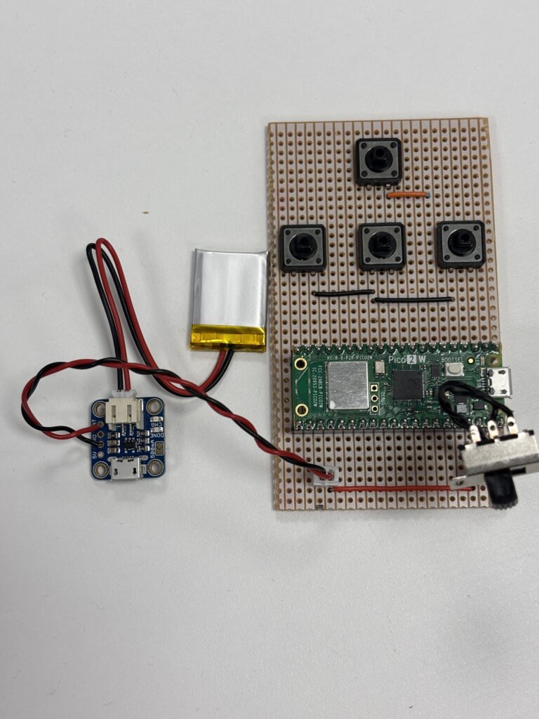
    The controller used on the previous version of the has been retained, and allow you to create a sequence of commands to send to the buggy via simple button presses:

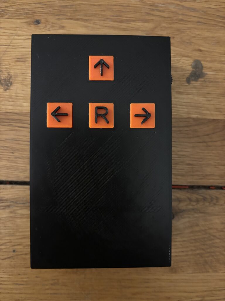
    Clicking once on the Left, Up and Right arrow buttons will send a single command to the buggy which will be queued until the ‘R’ button (run sequence) is subsequently pressed. For example, pressing ↑, ↑, ← followed by the ‘R’ button would make the buggy move forwards twice (each forward movement moves the buggy 200mm) followed by a 90° left turn.

    Commands are transferred from the hand-held controller to the buggy via bluetooth low energy. This was one of the most challenging aspects of the buggy build, as the details of bluetooth communications between a Raspberry Pi Pico (used in the hand-held controller) and the Arduino Uno R4 are not well documented and took quite a long time to figure out!

    The initial trial was very positive and the buggy seemed to run quite accurately, making accurate forward movements and turns. But the acrylic chassis was rather flimsy and flexed with the mass of the motors and large Lipo battery. So it was decided to construct an entirely new 3D printed chassis from PLA:

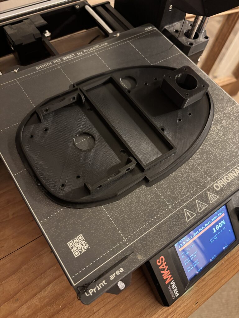
    The underside of the buggy (where the stepper motors are attached) is shown above just after it had finished printing. Some additional support brackets were also needed to house the on/off switch and support the Arduino Uno:

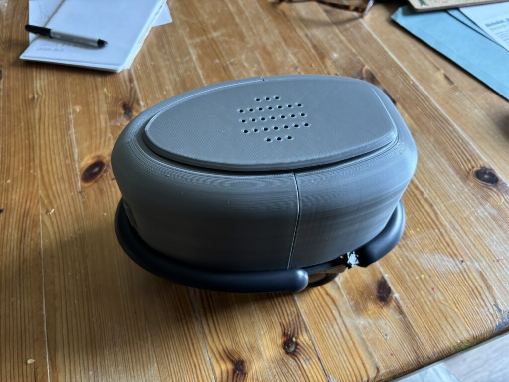
    The latest version of the buggy using the new 3D printed chassis is shown below:

    The 3D print files (.stl) and code for the Arduino and Pico will be made available soon, so that you can download and build your own programmable buggy.

    Below is a video demonstrating the buggy and how the controller is used to upload simple sequential programs:

  • Robot Programming Made Simple (Update)

    The robot buggy was tested at Rix Inclusive Research to see how well it worked (in principle) and although the controller (designed by Levi) communicated well with the Robot and commands were successfully sent to the robot buggy itself via BlueTooth, the buggy was reluctant to move in a straight line.

    DC motors are never quite the same in terms of their performance, so one was clearly stronger than the other resulting in the buggy turning right when it should have moved straight.

    To counter the effect of dissimilar motors, a pair of trimmers were added (10K pots) that were used to add a small amount of ‘trim’ to each motor – speeding the motor up or down according to what was required. Although partially successful, it was quite difficult to get consistent straight line performance.

    To try and persuade the buggy to move in a straight line, an LSN9DS1 accelerometer/gyro module was added to help control the movement, constraining the movement. This calculates yaw and corrects movement away from a straight line, which is looking promising although some final tuning is required.

    Another upgrade in the pipeline is the addition of wheel encoders. Due to the space limitations of the existing wheels and motors, the encoders needed to be reflective. To enable this, two disks of acrylic were cut and engraved so that an IR LED would reflect from the shiny surface (painted with a white marker) and not reflect where the acrylic was engraved (in between the white marks):

    The encoders themselves were 3D printed form PLA and each contains an IR LED and photo transistor set at 45 degrees:

    These have yet to be tested, but the idea is to get better control of the forward motion. The buggy needs to move a fixed distance each time a forward command is encountered. Currently, the forward movement is controlled using a simple timer. It’s not very accurate!

  • Robot Programming made Simple

    We are developing a simple, programmable robot buggy designed to make robotics accessible to a much wider audience. The core idea is to replace traditional text-based coding with tangible, tile-like objects that represent commands and actions. By arranging these tiles in sequence, users can create programs without needing prior programming knowledge. This approach lowers barriers to entry, supports inclusive learning, and empowers individuals, especially those with learning disabilities or limited technical experience, to engage creatively with robotics. Our goal is to transform programming into an intuitive, hands-on activity that fosters participation, exploration, and confidence.

    The buggy is a modified Cybot (which stems from around 2001) and adapted to use an Arduino Uno R4 Wifi microcontroller. The big grey box underneath the Uno is the rechargeable battery:

    Modified Cybot

    This project aims to democratize robotics education by creating a simple, programmable robot buggy that can be controlled using tangible, tile-like objects instead of traditional text-based coding. The core concept is to design a physical programming system where each tile represents a specific command or action, such as ‘move forward’, ‘turn left’ or ‘pause’. Users can arrange these tiles in sequence to form a program, which the robot interprets and executes. This approach removes the cognitive and technical barriers often associated with conventional programming, making robotics accessible to individuals with diverse abilities, including those with learning disabilities or limited digital literacy.

    The system will integrate a robust yet intuitive interface that translates tile arrangements into executable instructions for the robot. By leveraging inclusive design principles, the project seeks to foster creativity, problem-solving, and confidence among users who might otherwise be excluded from STEM activities. The tangible programming paradigm encourages hands-on engagement, collaboration, and experimentation, transforming programming into an approachable and playful experience.

    Ultimately, this project envisions a platform that can be used in educational settings, community workshops, and maker spaces to promote equitable participation in technology. By bridging the gap between physical interaction and computational thinking, the robot buggy serves as a stepping stone toward a more inclusive future in robotics and programming.

    The body of the Robot Buggy is based loosely upon the robot ‘tortoises’ by Grey Walter (with a little modification to the body shape and the addition of a speaker:

    First Steps

    The first step in this process is a robot that receives simple forward, left, right and stop commands via a hand-held bluetooth controller. Pressing a button on a controller moves the robot a fixed distance. This has some advantages in that it provides:

    Immediate Feedback: Pressing a button and seeing the robot move a fixed distance creates a clear cause-and-effect relationship, which is fundamental to understanding programming logic.

    Discrete Actions: Each button corresponds to a single command (forward, left, right, stop), which mirrors the idea of individual instructions in a program.

    Sequencing: Even though the user is pressing buttons manually, they are effectively creating a sequence of actions. For example, forward, then turn, then stop. This helps build the mental model of how instructions combine to form a program.

    Scaffolding: Starting with direct control via Bluetooth provides a low-barrier entry point. This can then be followed by providing tiles that represent these same commands, reinforcing the concept of sequencing without overwhelming the learner.

    This approach is very much aligned with constructivist learning principles – learners first experience the concept physically, then abstract it into symbolic representation (tiles), and eventually into digital or text-based programming.

    Bluetooth Control

    Not the easiest thing to program, especially when using two distinctly different microcontrollers using two different programming languages and different bluetooth libraries. The first problem here was figuring out which of the devices, using bluetooth terminology, has the role of ‘central’ and which should be ‘peripheral’. A little research on the web gave some answers, and this is what I found out.

    In Bluetooth Low Energy (BLE), the roles of central and peripheral are about who initiates the connection and who advertises availability:

    Peripheral: This device advertises its presence and waits for a central to connect. Typically, peripherals are simpler, low-power devices like sensors.
    Central: This device scans for peripherals and initiates the connection. Centrals usually have more processing power and act as the ‘controller’.

    So the robot itself will act as the ‘central’ device, whilst the controller will be designated as a peripheral.

    The controller is a simple four button circuit board connected to a Rapberry Pi Pico 2 W and powered by a tiny Lipo battery with USB charger:

    It communicates with the Robot Buggy by sending simple integer values as instruction codes: 1: Turn right, 2: Go forward, 3: Stop, 4: Turn left. We’ll use a minimalistic protocol where each command is a single character sent over Bluetooth:

    2 → Move forward a fixed distance (e.g., 10 cm)

    4 → Turn left by a fixed angle (e.g., 90°)

    1 → Turn right by a fixed angle (e.g., 90°)

    3 → Stop immediately

    This keeps communication lightweight and easy to parse on both devices.

    The simplified robot interface will be trialled by non-programmers by constructing simple sequences of instruction to move the robot around an obstacle course fro a starting location to a given target location.