Category: Uncategorized

  • 3D printing

    Reading University has a 3D printer, which we planned to use for this project. It uses ABS, which is durable and despite only being available in one colour,c an be relatively easily painted if necessary.

    The printer is compatible with Solidworks (or anything else that produces .STL files), which allows for precisely-made parts to be produced to scale.

    The case, littleBits connectors, and the three ‘top’ designs have been printed (still learning to use the camera!):

    P1150924

    This is the hex-top. It has had to be extended upwards to accomodate the internal parts.


    P1150931This is the dome top- it was tall enough already. The shaft of the rotary switch used to select the sound has been cut to fit.


    P1150934This is the original ‘pie’ top, again, extended to fit.


    The current design makes them relatively easy to change, but this does mean that the tops could be removed by a user. Future versions will require bayonet lugs or some similar mechanism to hold the top on.

    The littleBits connectors are generally the right size, but the small prong and socket is too fragile in 3D-printed ABS. They are also slightly the wrong size and do not fit cleanly. It has already been noted that they will need holes for magnets and electrical connections, so future versions will incorporate these changes.


  • MERL planning

    Kate and I are planning to hold a preliminary sensory session with a group from Mencap at MERL in September. Hopefully this will be a good time to test out the audio prototype and some ideas planned for the Autumn sessions.

    Entrance to MERL
    Entrance to MERL

    We visited the museum and the archive at MERL

    Invisible Horse
    Invisible Horse
    duck basket
    Duck Basket
    Threshing Machine Working Model
    Threshing Machine Working Model

    We considered existing objects that could contain sensor and listened for sounds used in the existing collection.

    Listening to Crafts
    Listening to Crafts
    Display with sound
    Display with sound

    We found that videos are used in the museum although most of the films have no actual sounds of the activity instead a narrator describes the activity. The videos of crafts pictured below do feature sounds of the process.

    Harness Making
    Harness Making

    Here is a compilation of the range of sensors and outputs we can use, or could make ourselves (to be compatible with LittleBits) to get an idea of how much choice we really have! (the ones marked in bold are already available to purchase in LittleBits)

    Sensors: light, sound, bend, roll switch, toggle, motion, pressure, slide dimmer, pulse, time sensor, stretch, tilt, accelerometer, blow, proximity

    Output: fan, light, sound, buzzer, motor, vibration, rgb LED, bargraph, smell (based on olly factory/aroma company), video

    Also, LittleBits supply AND and OR logic gates which add complexity to the circuits.

    Just as a log: In our meeting last week, we also talked about practical ways to introduce and demonstrate the co-researchers to the concept of the different sensors overcoming the problem that the sensors don’t look like what they do (e.g proximity sesnsor looks like a phone). Here is a list of some of the ways we discussed:

    light sensor in a box, bend sensor in a foam noodle, pressure sensor in a stress ball or shoe, blow sensor in a windmill, motion sensor in a wand, accelerometer in a bottle with oil and water.

    Please feel free to edit this post with other ideas or if I have missed anything out!

  • Selecting sounds

    A circuit has been designed around the ISD1820PY chips which allows up to 12 of them to be used in a single device.

    As mentioned in previous posts, the method of selecting which sound ‘file’ to play or record must be kept as simple as possible. We also want to make every action or method of interacting with the device distinct. The main idea has been a rotating section, either a ring or the entire top of the device, which ‘clicks’ round.

    Colours, textures, or embossed indicators (numbers, braille, or abstract symbols) will be used on the top section to differentiate between the sections.

    The ‘golf ball’ design shown earlier, though it looks a little like a microphone and provides a good surface to grip, does not do this, and so a few other designs have been created.

    Image

    The first concept was a similar image to a ‘Trivial Pursuit’ counter, with the distinctive pie wedges. This design provides plenty of space on its top surface for indication markers (coloured surfaces are used to indicate the sections here, but can be replaced with other methods later). The grooved lines match up with similar grooves in the body of the device, allowing users to check if the sections are lined up correctly.

    ImageThis dome-shaped version should provide a more ergonomic gripping surface, at the cost of size. The curved surfaces are also harder to print or emboss indicator markers on.

    It should be the same white colour as the other designs- this screenshot is grey.


    ImageThis hexagonal one was created because I was looking at bolts earlier. It’s similar to the ‘pie wedges’ design in terms of usability and practicality.

  • Interaction test

    Showing the sound quality and methods of recording/playback on the prototype.

    Still needs a better speaker and some batteries, as well as the selection method!

  • Testing Little Bits Extended Kit

    Tested LittleBits Extended Kit with two brothers I know with Aspergers (Jacob, 15, Adam 9/10). Both are very able and social but still struggle with attention span. Both were initially intrigued by the packaging and colourful bits but Adam found it a lot more exciting and willing to try than his older brother and this report is from his experience.

    I explained very briefly about the colours and how the pink sensors have to be before the green output but he got it pretty quickly and was making circuits in no time. He understood how the light sensor worked and we made the LittleBits box sound an alarm when opened (see video) and also similar to a fridge we made the light turn on when opened and off when shut.

    After suggesting many of my own ideas about making a drinks stirrer, doorbell, he couldn’t see any point and preferred not to. On my part, a theme or plan of some sort would have encouraged more creativity. But, instead Adam made a really long circuit using every output possible and multiple switches. He understood that the first toggle switch controlled the power to everything, whilst the switches in between only controlled what he put after it, and if you put two switches together, both need to be on for the output to work.

    Creativity problems:

    – Having more outputs rather than simply buzzer, fan, light, motor would have been      beneficial (LittleBits starter pack combined with Extended kit gives more possibilities).

    Practicality problems:

    – LittleBits bits, are quite flimsy – when making a long circuit on the table, as soon as you lift it up, it falls apart and needs to be reassembled.

    – The bits are more difficult to attach together than it appears – Adam did struggle and it took him 4/5 attempts each time to attach them. – Magnets are not that strong so don’t repel enough to indicate it is the wrong way.

    – Fan output too weak for any of the projects we tried (couldn’t move a tissue!!)

    -Motion sensor didn’t function from close up or further away.

    https://vimeo.com/71506274

  • Sound Collector Module User Interaction

    The proposed user interaction model will enable the user to record, choose, listen and delete recorded sounds. The device is composed of a button, five RGB Leds, a bazel, speaker and a microphone. The device is fully compatible with littleBits connectors.

    IMG_20130731_112617


    – Recording a sound file 

    To record a sound the user simply maintains the button pressed until he/she will record the sound. While the device is recording, one of the five RGB Led lights RED (also to explore the tactile feedback). Once the user has released the button, the fade from red to white and begin to dim. A new recording will act on a new switched-off led.

    IMG_20130731_112629


    – Listening to a sound file

    The user can choose a specific sound to listen to by rotating the pointer of the bezel to a diming (white) led. To listen the sound the user simply presses the button. The sound is played and the corresponding diming led lights to green.

    IMG_20130731_112639


    – Deleting a sound file

    The user can choose a sound to delete by rotating the pointer of the bezel to a diming (white) led.  The user can delete the sound file maintain the button pressed for five seconds. The corresponding led switch off.


  • Developing tools to enable during prototyping workshops

    Thoughts on white board
    Thoughts on white board

    The image above shows the white board as we discussed the process of collecting sounds at Speke Hall in Liverpool We made two columns the one on the left documents all the activity needed and who did what to collect and work with sounds. The column on the right shows activity with proposed collection module.

    In the left hand column we found that although the Co-researchers did capture sounds on recorders as they went around Speke Hall they found it difficult to listen back to what they had recorded. They were also not able to engage much with the rest of the process as the sounds needed to be up loaded on to a laptop to be converted in to the correct file format to go onto the SD cards. While one or two Co-Researchers did review the sounds there were so many we need to edit and whittle down the amount for them to choose from. When choosing how the sounds were activated there was also alot of support needed and Nic built the interactive systems for their sounds.

    In the right hand column we noted down the activity of our sound collection module. The module would be able to capture a limited number of sounds up to 6 was suggested and would only be able to record for a short time around 20secs (this was determined by the cards we are using to make the module although I would like a longer time this would make the unit bigger?) The record button would be big and red and light up when recording and switch off when record space is full. To hear what was recorded you pull the cord that also acts as a lanyard so you can where the unit round your neck. This means the Co-researchers could make careful choices about which sounds they recorded, hear them back immediately and keep reviewing what they have. This would remove alot of activity that Nic engaged with on the laptop. The sound collection module has a connector at its base that would link it to the Little Bits kit so the Co-researcher would be able to plug in various sensors to trigger sounds directly to the module removing the need for Nic to connect stuff with Arduino. The module is designed to promote enagement for the Co-Researchers during the prototype workshops stage. We still envisage a stage of creating a more robust model that would enhance the Co-researchers ideas using the Arduino at later stage of development.

    Sound Collection Module Mockup with Little Bits connection at base. Red record button and cord to pull for play back and to wear round neck
    Sound Collection Module Mockup with Little Bits connection at base. Red record button and cord to pull for play back and to wear round neck
  • Summary of Tangible Programming projects

    TL; DR:

    A lot of the projects were for research and thus aren’t commercially available- cost has been estimated based on how much it would cost to recreate them.


    Project Physical complexity Mental complexity Durability Portability Cost Senses required
    Squishy Circuits 1 2 1 3 1 Touch
    Tern 1 1 2 3 3 Touch, Sight
    littleBits 2 3 1 2 4 Touch, Sight
    Tangible Programming Bricks 3 3 2 3 N/A – 3 Touch, Sight
    Electronic Blocks 2 2 2 3 N/A – 2 Touch, Sight
    Reactable 1 2 1 1 4 Touch, Sight, Hearing
    StoryRooms 1 1 3 1 4 Touch, Sight, Hearing
    Cuboino 2 3 2 2 N/A – 2 Touch, Sight
    GameBlocks 1 1 2 1 N/A – 2 Touch, Sight
    Dr. Wagon 1 2 2 3 N/A – 3 Touch, Sight
    Topobo 3 2 2 3 N/A – 4 Touch, Sight
  • Tangible Programming

    A potential future area of research for Sensory Objects is how to make programming easier for people with limited ability to use a computer. Previous iterations of the project have used Arduino microcontrollers, which are programmed in a derivative of C. Though it’s relatively simple for those with programming experience, it does require some knowledge of programming concepts like loops, decisions, and logic. Users also need to have reasonable vision, typing ability, and sufficient dexterity to connect cables and wires to the Arduino boards.

    To allow a wider audience to program, we would like to circumvent the computer usage part by providing a ‘tangible interface’ made up of physical objects which users can manipulate to create computer-readable instructions.

    Many projects have examined this before us. Here are a selection of them.

    http://blogs.reading.ac.uk/digitallyready/author/lvs02ka/

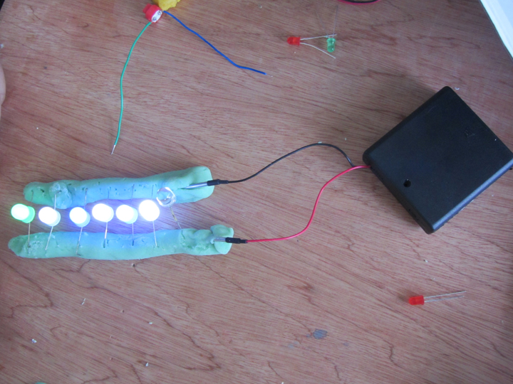
    Digitally Ready – a project run by Nic and Kate to get Art students using Arduinos.

    Mostly focused on LEDs, buttons and pressure sensors. Arduino control appears to have been minimal, main use of them was for powering Squishy Circuits.


    http://hci.cs.tufts.edu/tern/

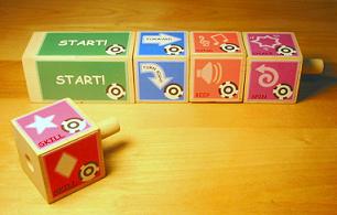
    Tern is a method of programming Turtles by the use of wooden blocks which have computer-vision readable images printed on them. The blocks represent a single instruction, like “go forwards”, “turn”, or “beep”.

    The blocks are not at all electronic, and once a program is ‘written’ it has to be read and interpreted by a computer with a webcam.

    No branching, logic, or loops are possible- all programs are straight lines of instructions.


    http://littlebits.cc/

    littleBits are small PCBs with magnetic connectors at either end. They are color-coded by category, and a single ‘bit’ is either an input (sensor) or output (effector). The bits signal to each other and provide power through their connectors.

    Programming concepts with the default set of bits are limited to IF (IF this switch is pressed, THEN turn on an LED) and AND (IF this switch AND this light sensor are activated, THEN turn on an LED). OR and NOT bits (‘inverter’) are available, as are dedicated AND bits. No loops are possible, but limited timing functions are present.


    http://xenia.media.mit.edu/~mcnerney/mcnerney-sm-thesis.pdf

    Image

    Tangible Programming Bricks are Lego bricks with embedded microcontrollers. Each brick performs a specified function. The bricks are stacked on top of each other to create a program. They communicate through electrical contacts on their top and bottom sides.

    Individual bricks’ functions can be modified by inserting ‘smart cards’ into a socket on one end, altering the time a brick is active for usually.

    Some bricks contain sensors or effectors such as IR communications, allowing multiple stacks to interact.

    Loops and conditional statements are possible and encouraged, as well as logic.

    Paper contains a detailed critique of the concept in the Discussion section.


    http://itee.uq.edu.au/~peta/WyethInteract.pdf Image

    Electronic Blocks are Duplo bricks with simple embedded electronics, much like LittleBits. Blocks are groups into categories by colour, and images are printed on the sides of the blocks to indicate their functions. Programs are created by stacking bricks on top of each other. Signals flow from the top of the stack to the bottom.

    Sensor blocks, effector blocks, and logic blocks are present. Conditional statements and AND, OR, etc are possible, but no looping or branching.


    http://www.reactable.com/

    http://en.wikipedia.org/wiki/Reactable

    http://www.youtube.com/watch?v=0h-RhyopUmc

    Reactable is a sound synthesis device which consists of a translucent table on which blocks are placed. A camera reads the underside of the blocks to determine their function and position. It also tracks fingertips pressed against the surface.

    A video projector provides extra UI elements on the table. These can be used as indicators or controls using the aforementioned fingertip sensing.

    Once placed on the table, the blocks can be used to create or adjust various qualities of sound. Moving blocks close to each other causes them to link up and affect each other. Rotating blocks usually affects some aspect of their function.


    http://www.nada.kth.se/kurser/kth/2D1624/PDF/Litteratur/p299-montemayor.pdf

     ImageStoryRooms are specialised rooms containing a variety of toy objects. A user enters the room with a ‘magic wand’ object, which can be used to define interactions between other objects. All objects present are wirelessly controlled by a researcher behind a one-way mirror via a computer. In response to the user performing an action intended to create a relationship between two objects, the researcher would attempt to provide a suitable reaction from the objects.

    Programming in this way is done by performing the actions in ‘programming mode’ with the wand, the researcher observes and notes the required interaction, then recreates it whenever the same action is performed out of ‘programming mode’.


    http://vimeo.com/56011933

    http://dl.acm.org/citation.cfm?id=2479578 Image

     Cuboino is a set of wooden cubes with channels cut in them. Most cubes are passive and direct the marble through only the use of the channels. They can be stacked and arranged to create a ‘marble run’. Active cubes can be snapped together to create devices. Some cubes have sensors for light, sound, button presses, or marbles passing over them. Others emit light, drop marbles, redirect marbles, etc. Some cubes simply provide power or transmit signals.

    Simple, stylised designs are used to indicate the function of each cube. All of them are made from plywood and are only really differentiable by the components visible on their surfaces.


    http://dl.acm.org/citation.cfm?id=1226999

    GameBlocks are large (~300mm) cubes with bright orange symbols on their tops. They are used by placing them onto trays which sense an arrangement of magnets in each cube’s underside. A central microcontroller reads each tray sequentially and performs the action associated with the block.

    No sensors are present- they are simply a method of instructing a sequence of movements by a robot.


    http://alfredosandes.tumblr.com/post/49060337074/dr-wagon-a-revolutionary-tangible-programmingImage


    Dr. Wagon is a method of programming a turtle (a wooden ‘wagon’ with a face on the front in this case), by means of a selection of snap-together wooden blocks. A ‘Start’ block is used to power the blocks, and communicate with the robot. Blocks are connected in a line under the Start block by four copper contacts, and held in place with magnets. Each block contains a PIC on a breadboard which communicates with the Arduino in the start block. When the start button is pressed, the Arduino polls the blocks under it sequentially. Each block sends the Arduino a single line of the program, which the Arduino then collates and transmits to the robot via radio. The robot’s on-board Arduino then compiles and runs the program.

    Block functions are indicated by laser-cut writing on the top surface of the blocks. Program flow is also indicated by laser-cut arrows on the edges of the blocks. This does indent the wood slightly, making it readable by touch.

    Loops and conditional statements are possible, but logic is not.


    http://www.topobo.com/

    http://www.youtube.com/watch?v=z4OcryzHiB0

    Topobo is a selection of plastic parts which connect via magnets, span connectors, and screws. Most parts are ‘passive’ in that they contain no motors or electronics. Some parts are ‘active’ and can move parts attached to them by means of motors.

    Active parts can be placed into a ‘learning’ mode during which they record any movements they are subjected to. Once set back to playback mode, they repeat this movement in a loop. This allows users to program a model of their own creation by manipulating it into performing the desired action.


  • Redesign #1

    If it was on wireframe rendering you could see the rotary switch and microswitch, but it's not, so you can't.
    Now with clicky dome thing, microphone hole, and string hole!

    Redesign #1

    Borrowed the LittleBits set from Nic, modelled the connectors. Trying to design a new body for the 3D printer, based on discussions today with Kassie and Kate.

    Collectionmodulemockup
    Collectionmodulemockup
    KassieCollectionModule1.
    Kassie test Collection Module
    KassieCollectionModule2jp
    Kassie test record button on Collection Module
    Kassie tests pullcord idea for hearing a recording CollectionModule
    Kassie tests pullcord idea for hearing a recording Collection Module